
Introduction#
I built a word clock in the Icelandic Language as a Christmas gift for my wife. I had a ton of fun building it and learned a lot along the way. It was also featured in the local paper.

This is the final product. The clock reads “klukkan er fimmtán mínútur yfir þrjú” which literally translates to “the clock is fifteen minutes over three” (or said as a native English speaker might “the time is fifteen minutes past three”). The clock also shows a special birthday message on my wife’s birthday - keep reading to see that in action!
The design was largely based on a reddit post I saw. While working on the project I had contacted the poster to ask why he had chosen to use two Arduinos. Turns out he was having trouble controlling both the lights and interfacing with the RTC (real-time clock) module. After a bit of chatting we were able to get his design down to just one Arduino.
I used an Arduino Uno and a breadboard to construct the initial clock. Since then, I have improved upon the design and used EagleCAD to design a custom PCB. In this post I will go through my initial design of the breadboard version and then share some pictures and details about the PCB version. All the code (for both versions) is available on Github .
Breadboard Version#
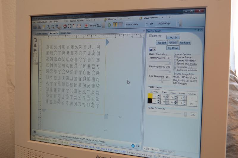
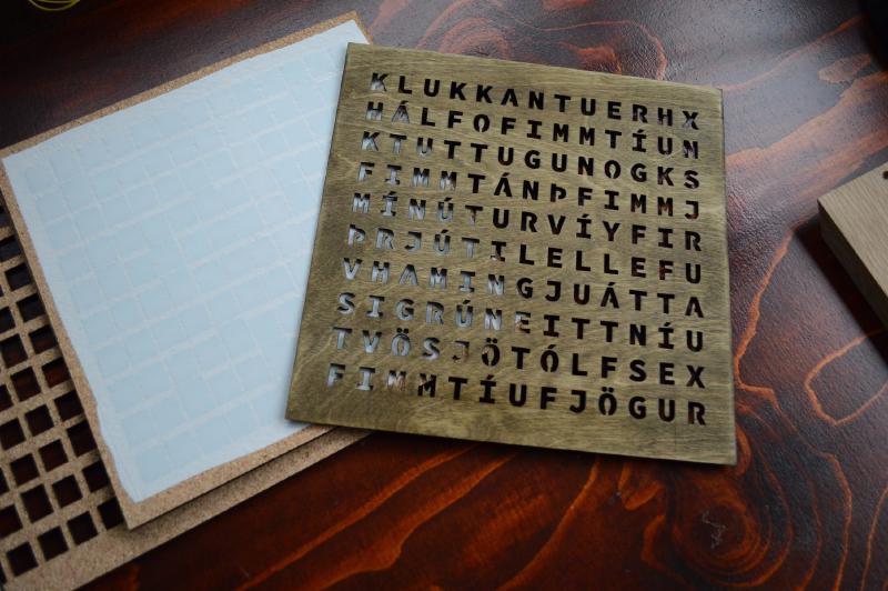
I started the project by laying out the letters for the clock in Adobe Illustrator. I was able to export an SVG from there and load it into the program that drives the laser cutter. I had never cut anything out with a laser cutter previously but a friend of a friend at the University of Iceland very generously donated his time, expertise, and access to an actual laser cutter to the project.
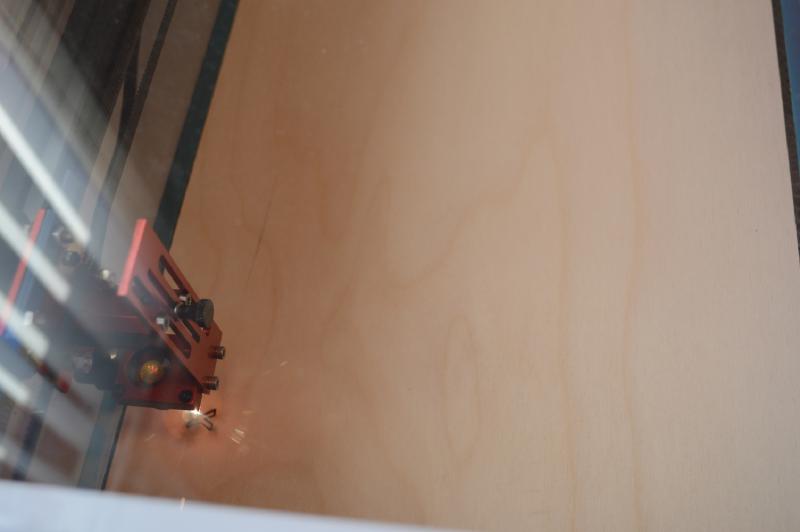
We went through a few pieces of wood before getting the settings right. We had to balance the intensity of the laser, the speed at which it moved, and the thickness of the wood. If the wood was too thick we tended to set it on fire and couldn’t get a nice finish, but if the laser moved too quickly or wasn’t at a high enough intensity then we wouldn’t consistently cut through the wood in all places we wanted to.
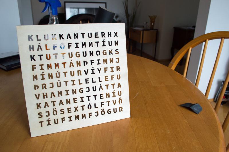
Once we get the settings right it only took a quick sanding to get the face of the clock looking great. Not seen in this photo, but I did eventually stain the face with a wood stain from the local hardware store.
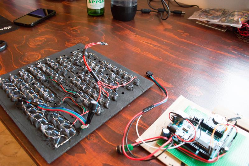
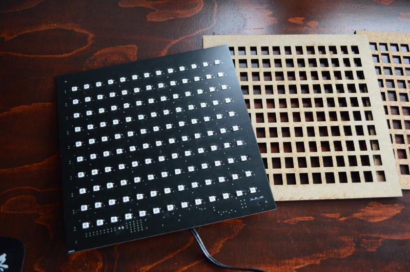
On the left is the wood panel I used to mount all of the LEDs. I had also cut this out with a laser cutter since I had access to it, but it could have just as easily been done with a drill and a bit of patience.
Each LED has a current limiting resistor. In theory it would have been possible to use one current limiting resistor, but if one does the math it would have needed to be able to dissipate more heat than made sense for a project like this.
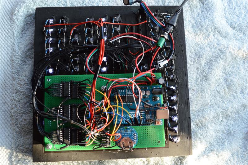
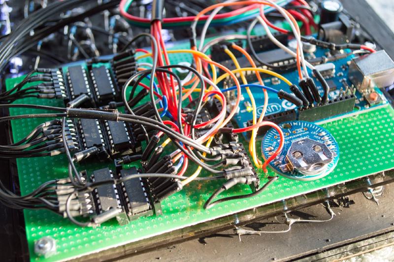
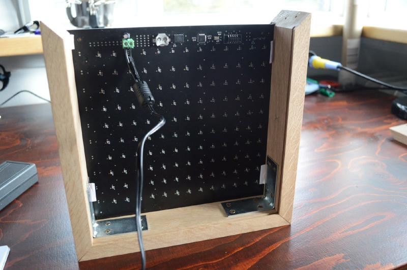
Here I have the “brain” board mounted on the back of the LED panel. It consists of a few components:
- The Arduino does all the logic. It will change what words are illuminated, what button presses do when setting the time, etc.
- The circular bit is an RTC module and keeps track of the time (even when the clock is unplugged). The Arduino’s internal clock can drift minutes per day (depending on the quality of the Arduino).
- The black DIPs are three pairs of shift registers and transistor arrays (located next to each other horizontally). The shift registers are used to expand the number of output pins I have access to (I use one pin per word). The transistor arrays are controlled by the shift registers and drive the LEDs because the shift registers can’t reliably handle the current required to power the LEDs directly.
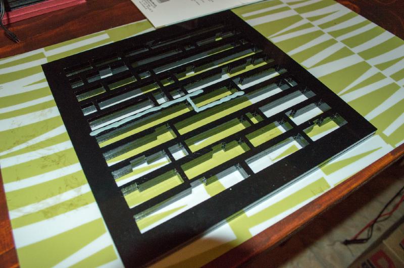
I needed a gasket to sit between the LED mounting panel and the face of the clock so that when one word lit up the light didn’t bleed into the surrounding letters. I had a local shop cut out a gasket from a thick piece of black acrylic but I was concerned light would still make its way between the acrylic and the LED panel so I tried to use some sticky tack. The sticky tack was not a good solution as it was just too difficult to get a thin and consistent layer around all the words. I wound up using some automotive gasket maker which worked well but I think it was overkill. I found a much better solution which I’ll show later in the section about the PCB version of the clock.
For LED diffusers I had the same shop cut out the appropriate shapes from a thinner piece of white acrylic and held them in place with glue. This was insanely time consuming and not a solution I would recommend - what I came up with for the PCB version was much less time consuming (and much cheaper).
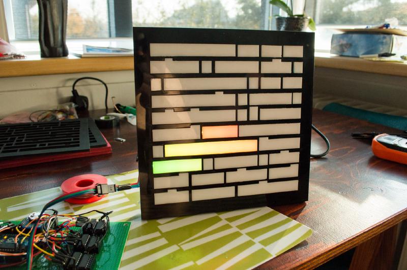
Getting to this point was a great feeling - I could finally get a real peek at what the final product would look like.
Here I have the birthday message “til hamingju kata” displayed which just means “happy birthday kata”.
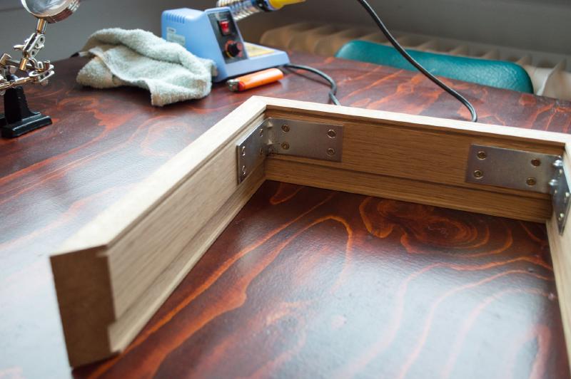
Next was the frame. This is something I outsourced as well as I just didn’t have the tools or space for it, but something I would like to do myself in the future. It’s not very complicated, just a very thick picture frame with a notch in it for the LED panel and face to slip into. There is also a small notch for the back of the clock to slip into.
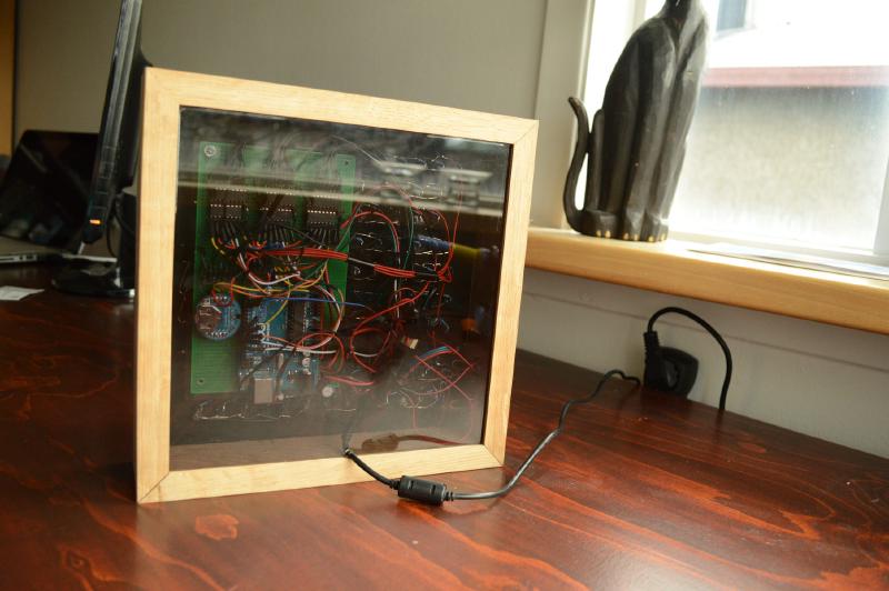
Like the reddit post I followed I chose to use an translucent acrylic panel for the back of the clock; I think it’s really cool to be able to see the insides. If one looks very close they can see the buttons used to set the time wired into the right side of the frame (as seen from the back). There is a mode button and an increment button. The mode button flips between year/month/day/hour/minute (and a birthday demo mode) and the increment button changes the values.

The final product as seen from the front one more time. My wife loved it and it was just a blast to build.
Now, onto the PCB version where I incorporated some of the lessons learned building this version.
PCB Version#
I used EagleCAD to design a custom PCB for this version of the clock. Here I used individually addressable LEDs so now I could control each letter instead of one word at a time, and I could change the colour of each letter instead of just the “happy birthday” letters. I soldered on all of the SMD LEDs by hand which was time consuming and error prone, but I managed to do it without damaging any of the pads.
If I ever made a third version I would make the clock consist of many smaller PCBs (e.g. one for each row) instead of one big board. There are a few reasons I think this would be better:
- I could get a better price on each PCB as I would be ordering more units.
- When one board was inevitably bad it would mean less waste as it’s just a row that would need to be tossed.
- The solder stencil would be cheaper and I could get away with a relatively small oven.
The “brain” is essentially still just an Arduino. I created a circuit on the back of the PCB for a very simple Arduino and flashed the Arduino bootloader to it. With that I could upload standard Arduino sketches to it. Like the LEDs, all hand soldered!
The LEDs I chose use a one-wire protocol and so I only needed one output pin from the embedded Arduino to control all of the LEDs. This meant that I didn’t need the shift registers nor the transistor arrays. The downside is that the addressable LEDs were significantly more expensive than just plan white LEDs.
I simplified the design of the gaskets greatly this time around by using cork. It was cheap, easy to cut, and slightly compressible so I could get a very good seal but pressing all the layers together tight before slipping them into the frame.
The diffuser is also much simpler here. Rather than cutting out separate pieces of acrylic I found a plastic film from 3M that is cheap, translucent, and has an adhesive on one side. It doesn’t have the shine to it that acrylic does but I found that at a normal viewing distance one could not tell the difference between the plastic film and the white acrylic.
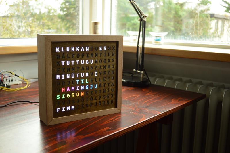
This is the final product, which looks pretty much the same as the breadboard version when viewed from the front. I sold this particular clock to someone who lives in the north of Iceland (whose significant other is named Sigrún).
Thanks for reading!