
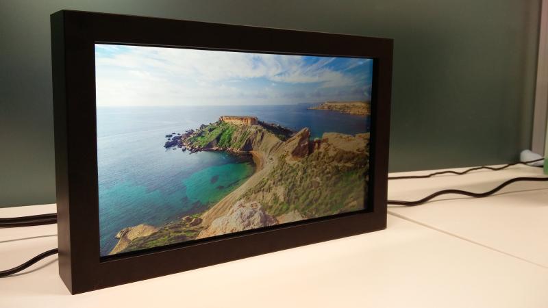
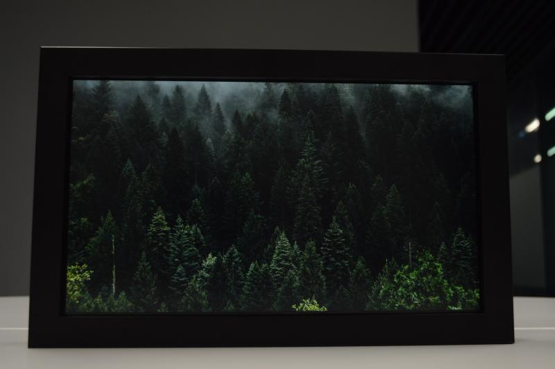
Let’s start with the final product! This is a digital picture frame I built (with my classmate Gunnar) for our Embedded Systems and IoT course at Reykjavik University. It’s also going to be my wife’s Christmas present, so we made sure to put a lot of extra love and care into it. We used a Raspberry Pi, an LCD panel from a laptop, and some other hobbyist components I’ll go over. You connect this picture frame to your home WiFi network to configure it via a web interface, or upload pictures to it with FTP. I have the schematic and all of the code for it on Github .
Here we can see the auto-dimming feature at work. I emulate a dark room by covering the light sensor. I use increasing exponential decay to calculate the brightness, but it’s a bit difficult to truly show that in action. When I performed tests on this feature, I found I liked the way exponential decay worked more than I liked a simple linear relationship between ambient light level and brightness.
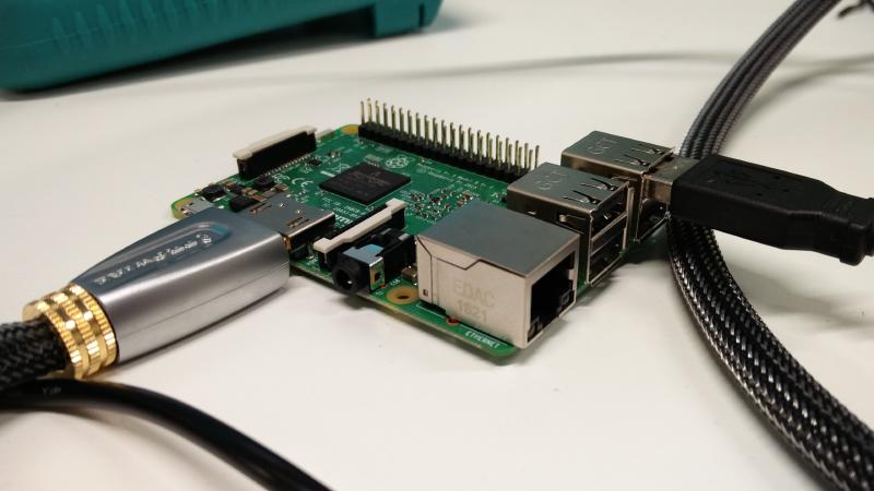
This is a Raspberry Pi 3 I got as a birthday gift. Always knew I would put it to good use. Thanks Jerome!
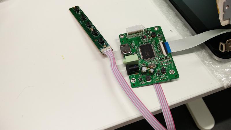
I ordered this guy off of eBay for ~20USD. Its the controller board for the LCD panel I used. I had an extra LCD panel for my laptop laying around after I ordered the wrong one when mine needed replacing. Its expensive to ship things to and from Iceland, so I didn’t bother with trying to return it.
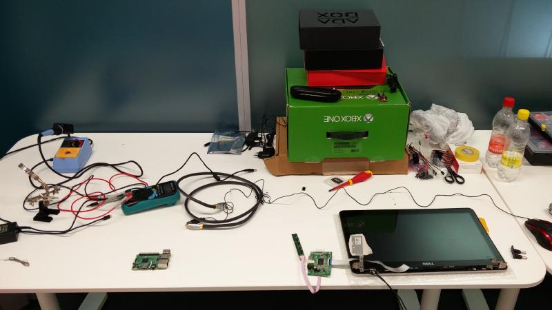
DIY electronics projects always take up way more space, and become way more messy than initially anticipated. This is when things were still relatively sane.
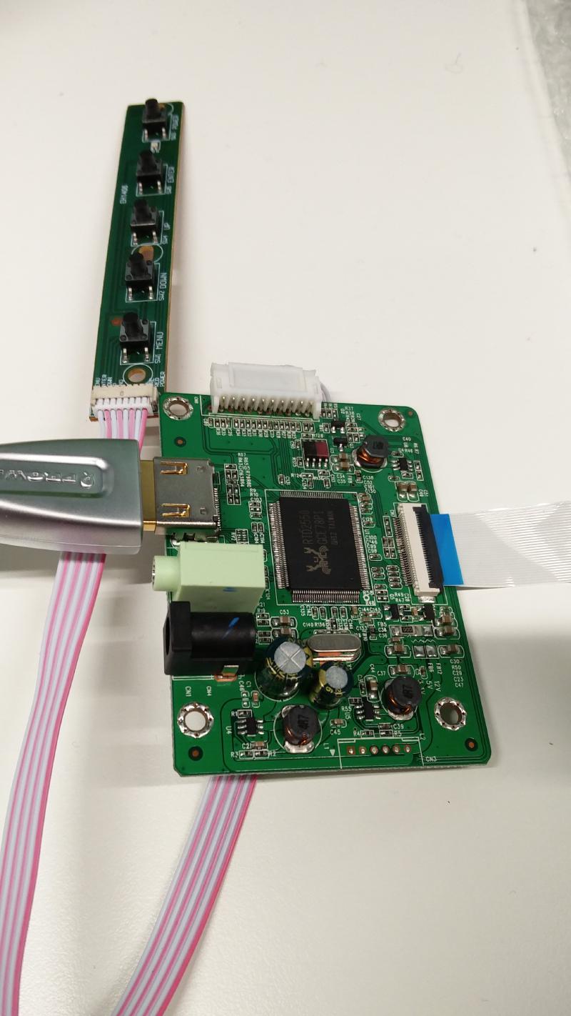
The Raspberry PI connects to the controller board with an HDMI cable, and then the controller board connects to the LCD panel with an eDP (embedded display port) ribbon cable. The buttons do what you would expect the button on the side of a monitor to do - open a menu to control brightness, color, etc. The final product doesn’t include these buttons.
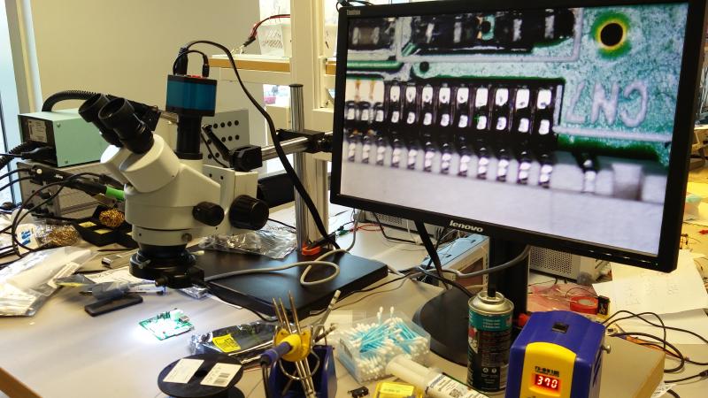
I wanted to be able to control the brightness of the display directly from the Raspberry Pi, but since HDMI doesn’t support brightness controls, I had to do a bit of extra work. I looked up the data sheet for the controller board and found the PWM (pulse width modulation) pin that controls the brightness of the LCD panel. I took the board over to the electronics lab at my university as they had a microscope we could use. The pins were pretty tiny, so this helped a lot.

Here you can see we soldered on two wires. One was for enabling the backlight (which I didn’t wind up using), and the other was the aforementioned PWM pin.
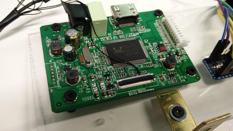
All soldered up!
This controller board remembers the settings a user enters with the buttons we saw earlier, even after power has been removed. So what I did was set the brightness to 0 with the buttons and then removed the buttons board. From here on out the Raspberry Pi is in charge of brightness!
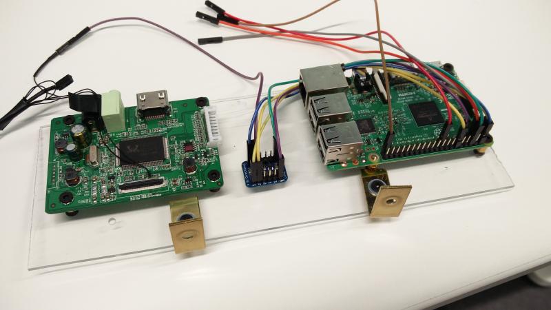
I used a spare piece of acrylic to mount the LCD controller board and Raspberry Pi on. The little guy in the middle is a logic level shifter.
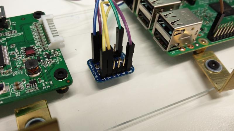
I use the logic level shifter to convert a 3.3V PWM signal from the Raspberry Pi to a 5V PWM signal that I connect to the PWM brightness control pin on the LCD controller board. The specs I read said the brightness control should be between 0V to 3.3V, but when I measured with my multi-meter I saw 0V to 5V.
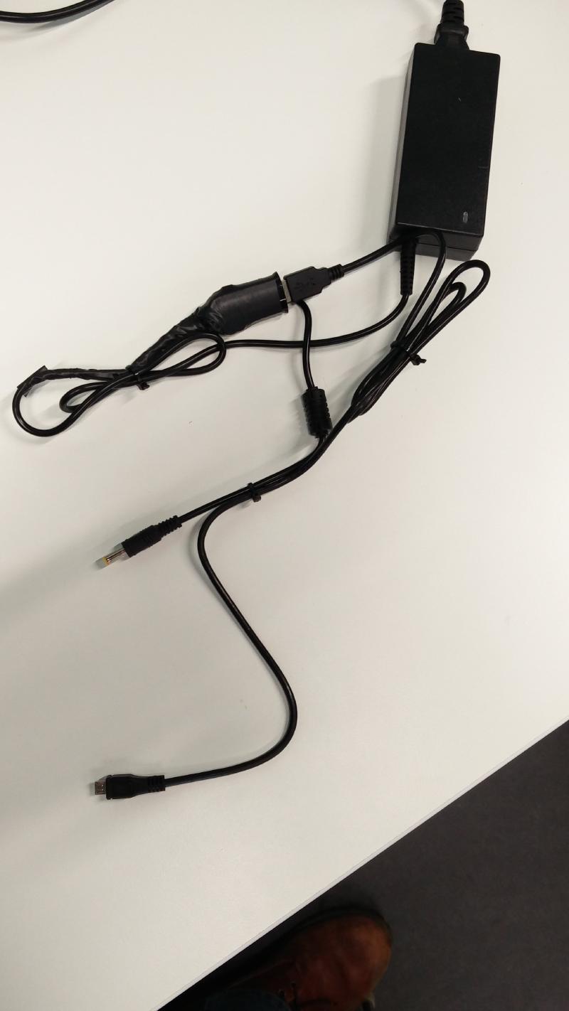
The controller board takes 12V, but the Raspberry Pi takes 5V. I bought a USB car charger to step down the 12V from the power supply to 5V, and then use a standard micro-USB cable to connect the Raspberry Pi to the power supply.
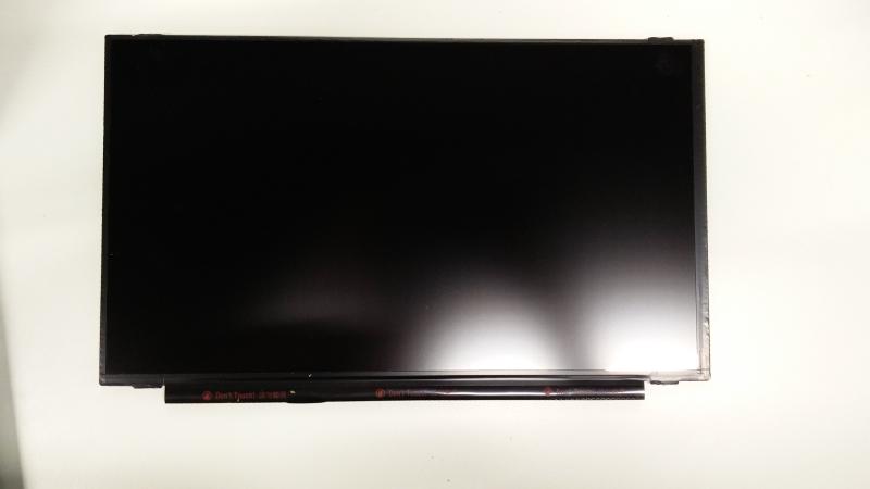
The LCD panel is removed from the laptop screen assembly, and is ready to be put into the frame.
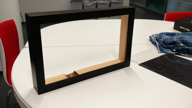
I had a local frame shop make a frame for me. I like their work, so I keep going back when I need anything frame related.
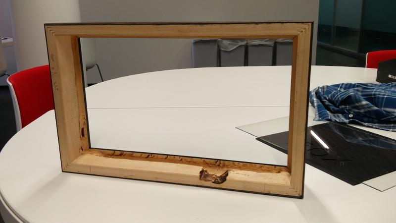
I had to carve out a bit of the bottom and side to accommodate the screen. You can see a black piece/stripe along the bottom of the LCD panel in the images above which contains some circuity for the panel.
Let’s call the result rustic. I didn’t really have the proper tools on hand to do it properly, and the frame was already assembled when I got it. If I were to do this again, I would make sure this was all carved out before the frame was assembled as it would be way easier to use the proper tools then.
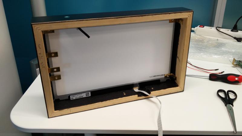
The frame also came with a piece of glass. Here I have placed the glass and the LCD panel into the frame and secured them in place with some L-brackets. The extra L-brackets on the left are to hold the power supply.
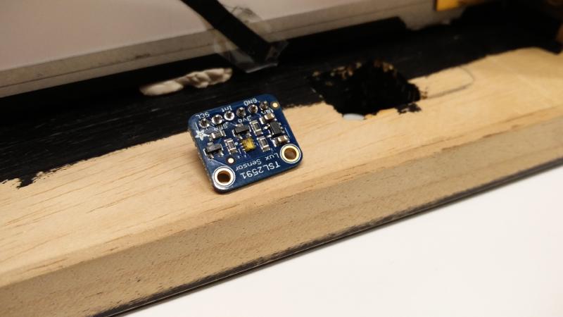
This is the light sensor I used. Its relatively inexpensive and available from Adafruit. I chose it because it has its own ADC (analog to digital circuit), and the Raspberry Pi has no ADC pins. I use the readings from this to add an auto-dimming feature to the picture frame. I created a small program that continually polls this sensor and then adjusts the brightness on the screen accordingly via the PWM pin I interface with on the LCD controller board.
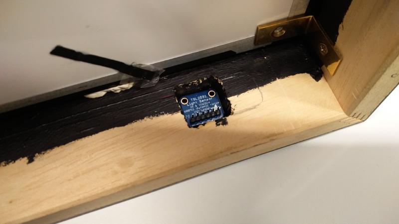
Light sensor mounted in the recess I carved out for it.
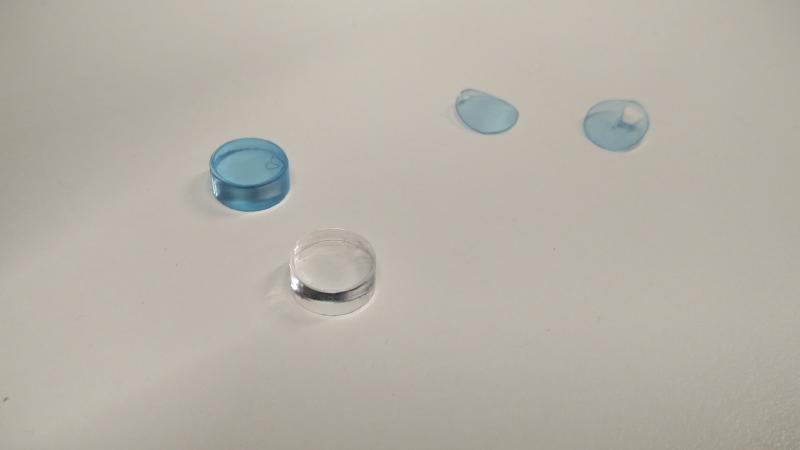
I had the engineering department at my university use their laser cutter to cut some acrylic discs for me to cover the hole for the light sensor. Originally I had just a pin hole drilled for the light sensor, but the angle at which light could enter was just too narrow. This solution wound up looking pretty cool though, so count me satisfied.
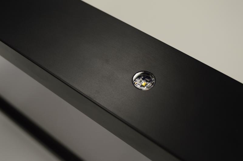
Here we can see a close up of the acrylic disc covering the light sensor on the top of the frame.
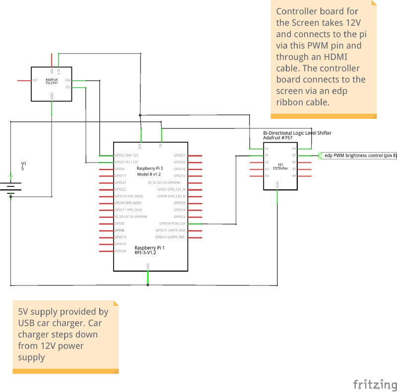
I used fritzing to whip up a very basic schematic for the project. Unfortunately developing a fritzing component for the LCD controller board was way more work than it was worth, so I just left some notes.

Everything inside the frame.
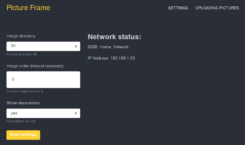
The digital frame runs a small web server. Once it’s connected to the WiFi, you can just pop open your browser and configure what you’d like to see and how. Currently the way to upload pictures is via FTP, but this could change in the future if I find the time and the will.
So nice.
I’m just having some fun here with my friend’s smart phone gimbal.
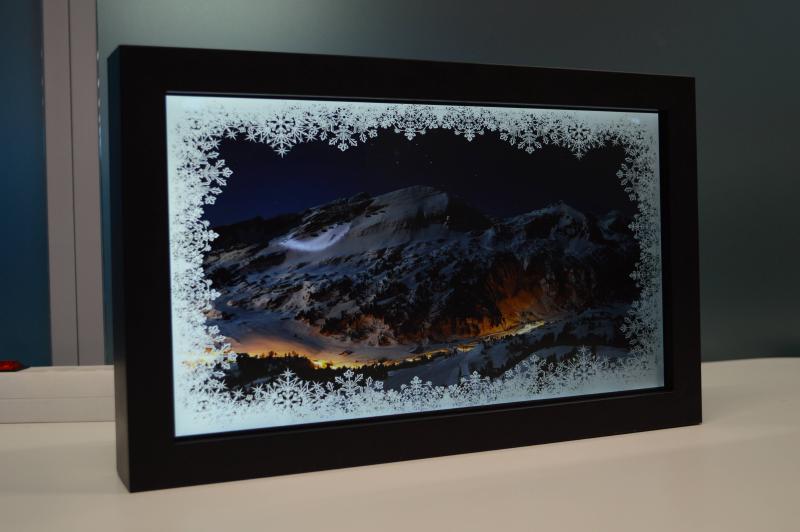
I added a last minute “seasonal decoration” feature. I take an image, in this case a snowflake border, and then superimpose it on each image before it is displayed. Currently I just have one for December.

The final product again. Thanks for reading!